Brake master cylinder
Structure and Components
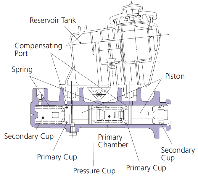
The brake master cylinder provides the necessary force to control the application of brake power and consists of the body, pistons, cups, springs, and reservoir tank. On the front of the body,
the primary cup creates hydraulic pressure when fluid is forced inside by the piston. On the back of the body, the secondary cup guides the piston and prevents fluid from leaking. In the center of the body,
the pressure cup separates brake fluid from the primary and secondary chambers. When the brake pedal is pressed, the primary cup is blocked away by the piston from the oil spill port leading to the reservoir tank,
and pressure in the cylinder rises as the fluid is fed through the brake lines. The secondary cup functions similarly and in synchronization with the primary cups.
When the brake pedal is released, the hydraulic pressure and the force of the return spring pull back the piston to relieve fluid back into the reservoir.
Main Functions
There are several variations (types) of brake master cylinders, which is determined by the structure, additional brake assist systems and vehicle application.
Though brake master cylinders can be classified into 3 main groups, all types share the basic functions required for braking action such as the generation, retention, and release of hydraulic fluid pressure.
without ABS
Conventional + Conventional
A brake system connected in a single circuit for both front and rear brakes.
with ABS
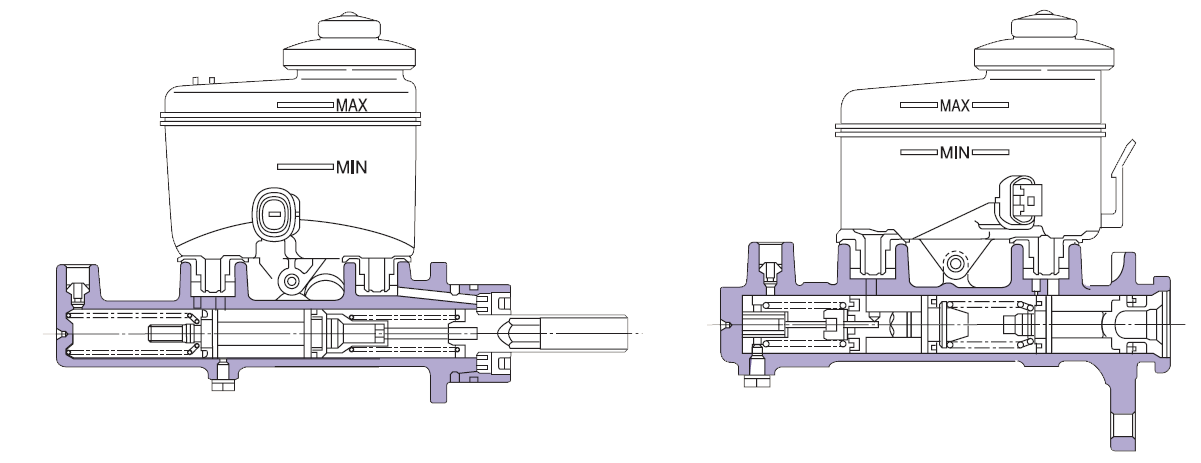
Long (Conventional + Conventional)
The cylinder body is designed as a Long Body, allowing two independent pistons to be arranged in series, resulting in a single piston, single circuit system for both front and rear brakes.
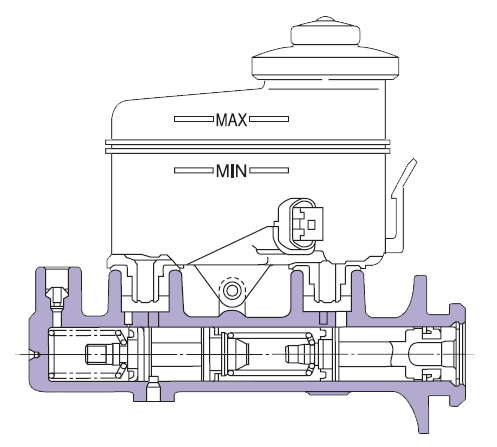
Center Valve + Conventional
A valve located at the center of the cylinder controls fluid flow, generating hydraulic pressure in a basic single piston, single circuit system.
With Additional Functions Such as VSC, etc.
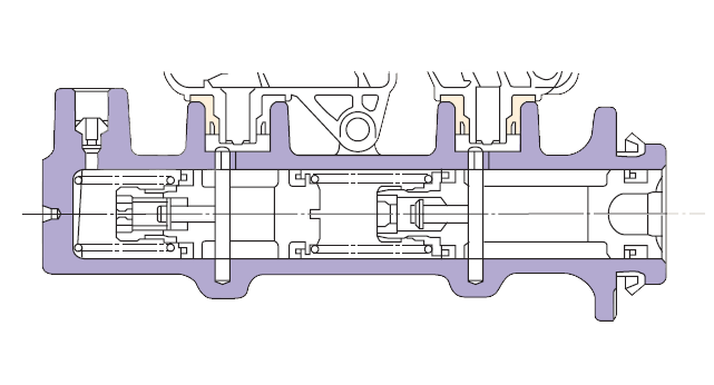
Center Valve + Center Valve
Both the primary and secondary circuits adopt the same center valve structure, allowing both circuits to operate in the same manner, resulting in uniform and stable pressure.
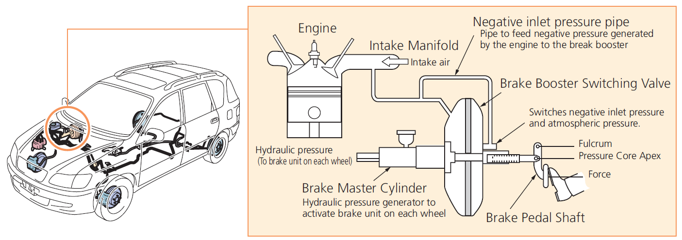
Brake booster
Function
Braking force is transmitted to the braking unit (caliper or drum) using a lever and hydraulic pressure. Due to the high forces required on the lever to dampen the speed of heavier vehicles,
the brake booster is designed to assist in applying the required pressure. The brake booster is a servo unit which uses negative pressure generated by the engine to the brake master cylinder.
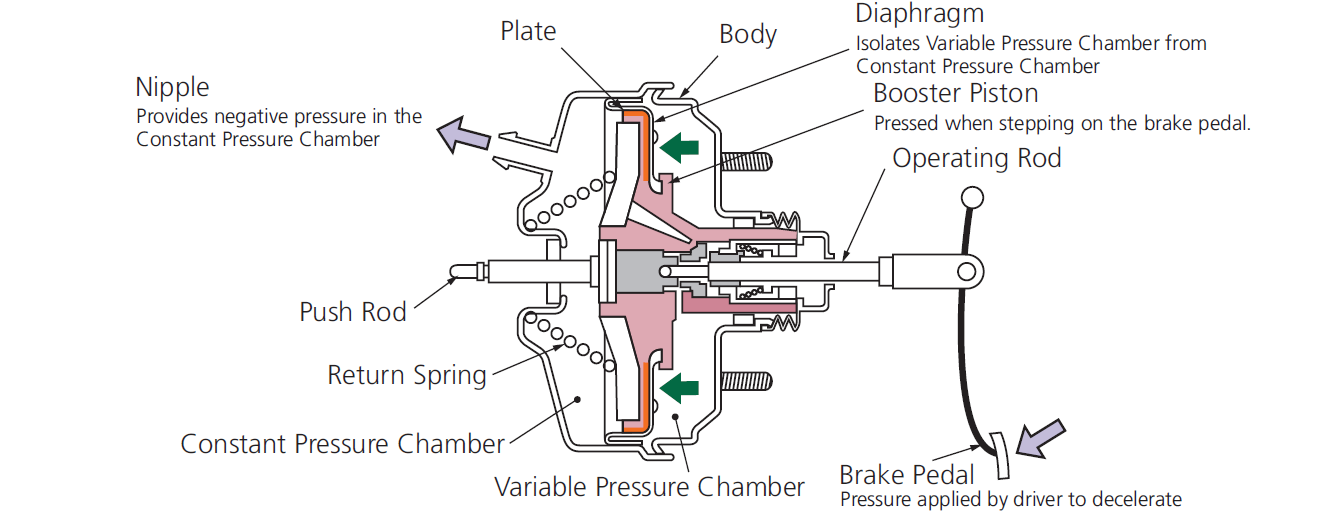
Primary Function
As the driver steps on the brake pedal, atmospheric air is introduced in the variable pressure chamber, producing a pressure differential between the variable and the constant pressure chamber.
The force generated by the pressure differential on the plate is transmitted to the push rod via the booster piston which pushes the piston of the brake master cylinder.
When the pedal is depressed, all components return to its original positions through the return springs. Dependent on the application and capacity, a single or tandem chamber design brake booster may be used.